Autoemx PLC
The Next Generation, Industrial-Ready PLCs with Built-In HMI Interface — Dual-core 240 MHz with Wi-Fi connectivity, scan time of 2.3 ms for 2000 boolean instructions, and a 2.8" touch screen. Built for engineers who demand more.
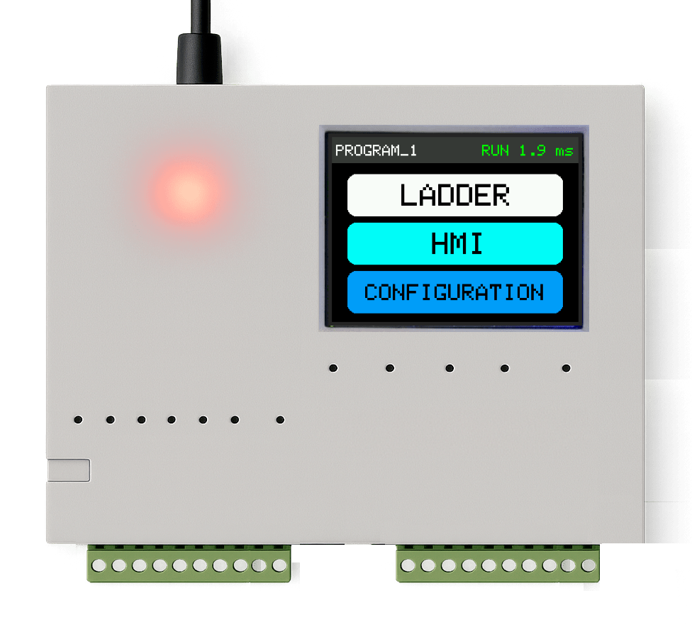
Flagship Compute Node
Autoemx Logic Controller
Eliminate disjointed, legacy multi-device loops. Autoemx integrates an explicit 7-inch capacitive user interface, high-density industrial telemetry loops, and decoupled operational processing arrays into one standardized DIN-rail system architecture built for extreme environments (-20°C to +70°C).
High Density I/O Matrix
32 DI / 16 DO / 8 AI / 4 AO
Bus Interfaces
Ethernet, RS-485, CAN Bus
Integrated HMI Panel
7" Touch, 1024×600 High Contrast
Execution Environment
IEC 61131-3 (ST, LD, FBD)
Production Infrastructure
Engineering & SMT Processing Array
High-Speed Multi-Layer Routing
Multi-layer layout generation optimized for high electrical stress areas, thermal stability, and strict signal transmission accuracy.
In-House SMT Line Production
Rapid, high-precision assembly featuring automated optical testing pipelines and strict thermal component setting profiles.
Edge Automation Design
Native logic linking involving complex field SCADA fabrics, dedicated fieldbus routes, and global corporate network integration options.
Operational Framework
Deployment Pipeline
Modeling & Limits
Functional range mapping, core thermal analysis, and precise safety condition planning phases.
Circuit Capture
Deep system layouts, functional execution modeling, and edge processing framework configurations.
SMT Synthesis
Automated creation of core physical loops on internally managed high-speed pick and place machines.
Validation Rollout
Volume orchestration setup, environmental compliance reviews, and life-cycle telemetry updates.
Economic Proof Metrics
Optimizing Domestic Automation Models
By unifying visualization screens, data logic blocks, and protocol conversions onto an integrated core node.
Eliminating overseas shipping bottlenecks by maintaining full layout and structural hardware controls directly in Pune.
Unrestricted access to the core hardware engineers who mapped the silicon paths, bypassing third-party vendors.
| Architecture Parameters | Ambivert Architecture | Legacy Import Arrays |
|---|---|---|
| Engineering Sync | Unified (Pune Facility) | Disjointed Assembly Layers |
| Component Topology | Integrated Compute Core | Multiple Hardware Enclosures |
| Deployment Lead Time | 3 to 5 Working Days | 4 to 12 Extended Shipment Weeks |
System Gateway Terminal
Initiate Architecture Review
More efficient together...
Data Endpoint
Voice Stream
Operational Center
Ambivert Technologies Pvt. Ltd.
Pune,
Maharashtra, India